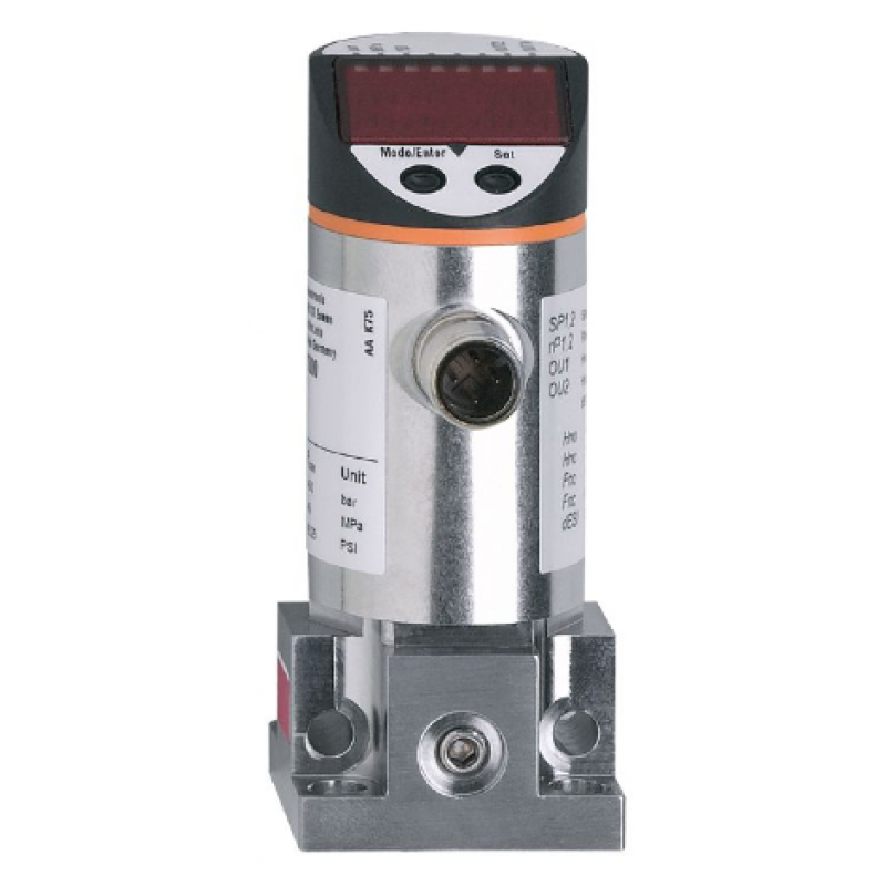
Product data sheet
Product Characteristics
Total number of inputs and outputs
Number of digital outputs: 2
Measuring range
0.... .250 bar
0... .3625 psi .3625 psi
Measuring range [MPa]
0... .25
System connections
Flange female thread: G 1/4; female thread: M6
APPLICATIONS
Special features
Gold-plated contacts
Design
with flange adapter
Media
Liquid and gaseous media
Conditionally applicable
for gaseous media pressures > 25 bar only on request
Medium temperature [°C]
-25.... .80
Burst pressure min.
850 bar
12300 psi
Burst Pressure Min [MPa]
85
Compressive Strength
400 bar
5800 psi
Compressive Strength [MPa]
40
Pressure
Relative pressure
Electrical Data
Operating voltage [V]
18.... .36 DC; (according to SELV/PELV)
Current loss [mA]
< 50
Insulation resistance min.
100; (500 V DC)
Protection class
III
Inverted phase protection
yes
Overvoltage protection
Yes; (< 40 V)
Power-on delay time [s]
0.3
Watchdog
Yes
Total Inputs/Outputs
Total number of inputs and outputs
Number of digital outputs: 2
Outputs
Number of outputs
2
Output signals
Switching signal; IO-Link; (configurable)
Electrical design
PNP/NPN
Number of digital outputs
2
Output function
Normally open/closed; (parameterizable)
Switching output DC voltage drop maximum value [V]
2
Continuous current load of switching output DC [mA]
250
Switching frequency DC [Hz]
< 170
Short circuit protection
Yes
Type of short-circuit protection
Pulse
Measuring/setting range
Measuring range
0.... .250 bar
0.... .3625 psi
Measuring range [MPa]
0... .25
Switching point, SP
2.... .250 bar
40.... .3620 psi
Switching point, SP [MPa]
0.2.... .25
Recovery point, rP
1.... .249 bar
20.... .3600 psi
Recovery Point, rP [MPa]
0.1.... .24.9
Setting step
1 bar
20 psi
Setting step [MPa]
0.1
Factory setting
SP1 = 63 bar
rP1 = 58 bar
SP2 = 188 bar
rP2 = 183 bar
Accuracy / Deviation
Switching point accuracy [% of measuring range value]
< ± 0,5
Repeatability [% of measuring range value] < ± 0,1; (temperature fluctuations < 10 K)
< ± 0,1; (temperature fluctuations < 10 K)
Characteristic curve deviation [% of measuring range] < ± 0,5; (temperature fluctuations < 10 K)
< ± 0,5; (linearity, including hysteresis and repeatability, limit values according to DIN EN IEC 62828-1)
Hysteresis deviation [% of measuring range value] < ± 0,25
< ± 0,25
Stability over time [% of measuring range value] < ± 0,05; (% of measuring range value)
< ± 0,05; (every 6 months)
Temperature coefficient zero [% of measured range value / 10 K]
0,2; (0.... .80 °C)
Temperature coefficient range [% of measured range value / 10 K] 0,2; (0...80 °C)
0,2; (0... .80 °C) .80 °C)
Reaction time
Programmable delay time dS, dr [s]
0; 0,2... .50 °C .50
Software / Programming
Parameter setting
Hysteresis/Window; Normally open/closed; Diagnostic function; Output polarity; ON delay, OFF delay; Damping; Display unit
Interfaces
Communication Interface
IO-Link
Transmission type
COM2 (38,4 kBaud)
IO-Link revision
1.1
SDCI standards
IEC 61131-9 CDV
Outline
No profile
SIO Mode
Yes
Required mater port type
A
Analog process data
1
2-digit output process data
2
Process cycle minimum [ms]
2.3
Supported DeviceID
Operation mode
DeviceID
default
308
Operating conditions
Ambient temperature [°C]
-20.... .80
Storage temperature [°C]
-40.... .100
Enclosure protection class
IP 67
Certification/Testing
EMC Electromagnetic Compatibility
EN 61000-4-2 ESD
4 kV CD / 8 kV AD
EN 61000-4-3 HF EMF radiation
10 V/m
EN 61000-4-4 Burst
2 kV
EN 61000-4-5 Surge
0,5/1 kV
EN 61000-4-6 Conducted immunity for RF field induction
10 V
Shock resistance
DIN IEC 68-2-27
50 g (11 ms)
Vibration
DIN IEC 68-2-6
20 g (10.... .2000 Hz)
Pressurized Equipment Directive
good engineering practice; can be used for Group 2 fluids; on demand for Group 1 fluids
Mechanical Technical Data
Weight [g]
382.5
Material
Stainless steel (1.4301/304); PC; PBT; PEI; FKM
Material (wetted parts)
Steel (1.4104 / 430F); Ceramic; FKM
Switching life
100 million
System Interface
Flange Female thread: G 1/4; Female thread: M6
Integrated limiter element
No
Display/operating elements
Display
Display units
3 x LED, green
Switching status
2 x LED, yellow
Function display
Alphanumeric display, 4 digits
Measured values
Alphanumeric display, 4 digits
Comments
Packaging unit
1 piece
Electrical connection
Connector: 1 x M12; Translator: A; Contacts: gold-plated


