Product data sheet
Main Software Functions
Applications and Purposes Function Description
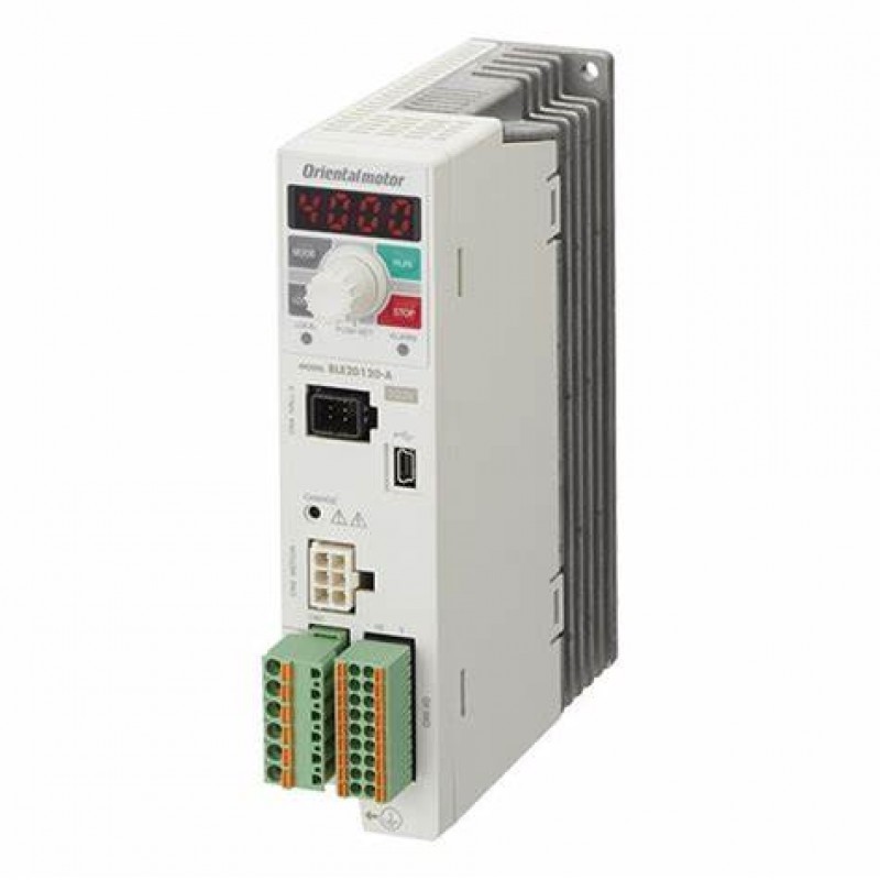
Checking the Motor's Generated Torque. Load Factor Indication It displays the load factor with the motor's rated torque as 100%. (Indication range: 0∼300%)
Displays the Output Shaft Speed after the
Gearhead. Gear Ratio When the gear ratio is set, it displays the converted speed.
Operating at a Speed within the Set Speed
Control Range. Speed Limits Setting It sets the upper and lower limit values of the speed.
Changing the Speed while the Motor is
Rotating. Speed Teaching Speed can be changed in the monitor mode while the motor is rotating.
Holding the Load during Standstill. Easy Holding Torque
An electrical holding torque can be generated while the motor is stopped. (Holding force up to 50% of rated torque)
Note Since the holding force is canceled when the power supply to the driver is turned OFF, it cannot be used to prevent falls
during standstill.
Reducing Shock during Starting and
Stopping. Shock Alleviation Filter This function softens acceleration and deceleration so that the load being transported does not experience sudden movement.
Checking the Reason for the Alarm
Generation. Alarm Alarm outputs include overload, incorrect connection, over voltage etc and can be identified easily. This allows for ease of fault finding
and swift corrective action.
Information Status of the Motor and Driver. General Information Before an alarm is output, an information output can be set to enable maintenance teams to be made aware of situations when the
motor maybe running outside of its normal conditions before going into alarm.
Set Data is Protectable. Edit Lock Set data is protectable, which prevents users from deleting or making unnecessary changes to data & parameters, from either the
control panel or the local PLC.


